
Table of Contents
EV Charging Equipment: Commercial, Fleet & High-Power Hardware Guide
Deploying electric vehicle supply equipment (EVSE) requires balancing grid capacity, power electronics, thermal management, and long-term hardware durability. Modern EV charging equipment serves as the critical bridge between medium-voltage distribution grids and high-voltage vehicle battery packs.
The hardware landscape has expanded beyond basic alternating current (AC) wall boxes. High-power commercial operations utilize direct current fast charging (DCFC) cabinets, dynamic load-balancing power skids, and Megawatt Charging Systems (MCS) tailored for commercial freight.
Selecting the right EV charging equipment involves evaluating power output, operational environments, thermal constraints, open protocol compliance, and total cost of ownership (TCO).
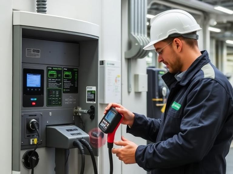
2. Core Classification Matrix of EV Charging Equipment
To match equipment to specific operational use cases, hardware is grouped by charging levels, current delivery profiles, and underlying electrical topologies.
┌─────────────────────────────────────────────────────────────────┐
│              EV CHARGING EQUIPMENT CLASSIFICATIONS              │
├───────────────────┬───────────────────┬─────────────────────────┤
│ Commercial AC     │ High-Power DC     │ Megawatt Class (MCS)    │
│ Level 2 (7-19 kW) │ Fast (50-400 kW)  │ Heavy Duty (1-3.75 MW)  │
├───────────────────┼───────────────────┼─────────────────────────┤
│ • Fleet overnights│ • Highway corridors│ • Long-haul trucking    │
│ • Workplace dwell │ • Retail stopovers│ • Transit bus depots    │
│ • On-board inverter│ • Cabinet rectifiers│ • Water/Maritime craft │
└───────────────────┴───────────────────┴─────────────────────────┘
A. AC Level 2 Commercial Equipment
AC equipment supplies utility power directly to the electric vehicle’s onboard charger (OBC), which rectifies AC into DC to charge the battery. Commercial AC systems operate between 208V and 240V split/three-phase AC. They use protective contactors, ground fault protection, and basic Control Pilot communication circuitry to manage power safely.
B. DC Fast Charging (DCFC) Equipment
DCFC hardware bypasses the vehicle’s onboard charger, feeding conditioned high-voltage DC current straight into the traction battery. Power conversion occurs inside an external cabinet using stacked modular rectifiers. DCFC hardware ranges from compact 50 kW urban units to 400 kW ultra-fast dispensers equipped with liquid-cooled cables.
C. Megawatt Charging System (MCS) Equipment
Designed for commercial trucking, heavy transport, and aviation, MCS equipment delivers up to 1,250V and 3,000A (3.75 MW peak). This hardware requires liquid-cooled contacts, automated robotic coupling options, and dedicated medium-voltage grid connections.
3. Hardware Technical Specifications: AC Level 2 vs. High-Power DCFC
Selecting hardware requires comparing electrical boundaries, thermal demands, and physical footprint requirements.
| Equipment Parameter | Commercial AC Level 2 | Standard DC Fast Charger (150 kW) | Ultra-Fast Modular DCFC (350-400 kW) |
| Input Voltage | 208V / 240V 1-Phase or 3-Phase | 480V 3-Phase AC (Delta/Wye) | 480V to 600V 3-Phase AC |
| Output Voltage Range | Pass-through AC (208–240V) | 200V – 1000V DC | 200V – 1000V DC |
| Max Output Current | 32A to 80A Continuous | 150A to 350A DC | Up to 500A+ DC (Liquid-Cooled) |
| Power Electronics Topologies | Electro-mechanical Contactors | Silicon IGBT Rectifier Modules | Silicon Carbide (SiC) MOSFET Modules |
| Peak Efficiency Rating | > 98.5% (Low conversion loss) | ~ 94.0% – 95.5% | ≥ 97.0% (High-density SiC) |
| Cooling Mechanism | Natural Convection / Air Fan | Forced Air Industrial Fan Array | Closed-Loop Liquid Glycol Chiller |
| Standard Connectors | J1772, SAE J3400 (NACS) | CCS1, SAE J3400 (NACS) | Dual SAE J3400 / CCS1 Liquid-Cooled |
| Compliance & Standards | UL 2594, UL 2231, SAE J1772 | UL 2202, UL 2231, IEC 61851-23 | UL 2202, ISO 15118, DIN 70121 |
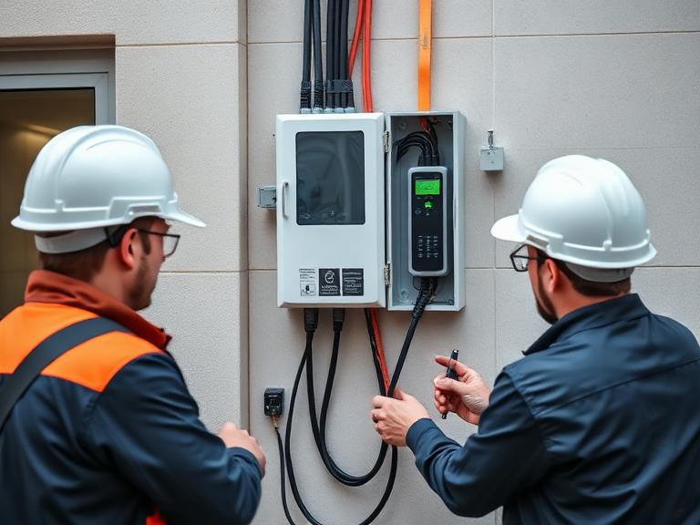
4. Internal Component Architecture of High-Power DC Charging Equipment
Understanding the internal sub-assemblies of a modern DC fast charging station helps engineers optimize maintenance, reliability, and heat dissipation.
                     ┌──────────────────────────────┐
                     │ 480V 3-PHASE AC GRID INPUT   │
                     └──────────────┬───────────────┘
                                    │
                                    ▼
                     ┌──────────────────────────────┐
                     │ Isolation Transformer & EMI  │
                     └──────────────┬───────────────┘
                                    │
                                    ▼
                     ┌──────────────────────────────┐
                     │ Silicon Carbide (SiC) AC/DC  │
                     │ Active Front-End Rectifiers  │
                     └──────────────┬───────────────┘
                                    │
           ┌────────────────────────┼────────────────────────┐
           │                        │                        │
           ▼                        ▼                        ▼
  ┌─────────────────┐      ┌─────────────────┐      ┌─────────────────┐
  │ Isolated DC/DC  │      │ Main Micro-     │      │ Liquid Glycol   │
  │ Buck/Boost Stage│      │ Controller Unit │      │ Cooling Loop    │
  └────────┬────────┘      └────────┬────────┘      └────────┬────────┘
           │                        │                        │
           └────────────────────────┼────────────────────────┘
                                    │
                                    ▼
                     ┌──────────────────────────────┐
                     │ DC Contactors & Safety Relay │
                     └──────────────┬───────────────┘
                                    │
                                    ▼
                     ┌──────────────────────────────┐
                     │ Liquid-Cooled Cable & Plug   │
                     └──────────────────────────────┘
Key Sub-Assemblies
- Active Front-End (AFE) Rectifier Stage: Converts incoming three-phase AC power into a high-voltage intermediate DC bus link. Modern systems use Silicon Carbide (SiC) semiconductors, which run cooler and reduce switching losses compared to legacy Silicon IGBTs.
- Isolated DC/DC Converter Stage: Adjusts output voltage and current to match the connected battery’s state-of-charge (SoC). Galvanic isolation protects the vehicle from high-voltage grid transients.
- Main Controller Unit (MCU): Runs low-level firmware to manage safety interlocks, monitor line isolation, handle digital handshake signals (ISO 15118 / DIN 70121), and manage OCPP communications.
- Liquid-Cooling Chiller Assembly: Pumps non-conductive glycol coolant through internal heat sinks and down the charging cable assembly. This keeps wire diameters light and easy to handle while managing continuous 500A loads.
5. Standardized Connector & Physical Interface Ecosystem
Connector designs differ across global markets, but North America and Europe are converging around high-performance unified standards.
┌────────────────────────────────────────────────────────────────────────┐
│                   PHYSICAL CONNECTOR TOPOLOGIES                        │
├────────────────────────────────┬───────────────────────────────────────┤
│ SAE J3400 (NACS)               │ Combined Charging System (CCS1)       │
│ • Shared Pin AC/DC Architecture│ • Separate AC Pins & Dual DC Pins     │
│ • Compact Ergonomic Form Factor│ • Bulkier Cable Assembly              │
│ • Up to 1000V / 400A+ Pass-thru │ • Legacy North American Standard      │
└────────────────────────────────┴───────────────────────────────────────┘
The Shift to SAE J3400 (NACS)
North America has rapidly transitioned toward the SAE J3400 standard (originally Tesla NACS).
- Shared Pin Topology: Unlike CCS1, which uses separate contacts for AC charging and DC fast charging, SAE J3400 uses the same two primary power contacts for both AC single-phase power and high-voltage DC fast charging.
- Safety Interlocking: High-speed relays and control pilot handshake logic ensure the charger never routes AC grid voltage across DC fast charging configurations, preventing component damage.
- Voltage Limits: SAE J3400 supports up to 1000V DC and continuous currents exceeding 400A without active cooling, or up to 500A+ when liquid-cooled.
$$\text{Shared Pin Efficiency Factor } (\eta) = \frac{P_{\text{Delivered}}}{P_{\text{Grid In}}} \times 100$$
6. Embedded Firmware, Protocols, and Software Management
Without robust software protocols, high-power EV charging equipment cannot safely initiate power delivery, process payments, or perform dynamic load management.
┌────────────────────────────────────────────────────────┐
│               STACKED COMMUNICATIONS LAYER             │
├────────────────────────────────────────────────────────┤
│ Charge Point Management System (CPMS Cloud Layer)     │
├────────────────────────────────────────────────────────┤
│ Open Charge Point Protocol (OCPP 1.6J / 2.0.1)        │
├────────────────────────────────────────────────────────┤
│ ISO 15118-2/20 Digital Handshake (Plug & Charge / V2G)│
├────────────────────────────────────────────────────────┤
│ High-Level PLC Signaling (DIN 70121 / IEC 61851)      │
└────────────────────────────────────────────────────────┘
Essential Communication Protocols
- ISO 15118 (Plug & Charge & V2G): Governs the digital link between the EV and the charger over Power Line Communication (PLC). Enables encrypted authentication, automatic billing without credit cards, and bidirectional energy flows (Vehicle-to-Grid / V2G).
- OCPP (Open Charge Point Protocol): The standard communication link between the charger hardware and the cloud backend (CPMS). OCPP 2.0.1 adds advanced cybersecurity, remote firmware management, and detailed hardware diagnostic reports.
- OCPI (Open Charge Point Interface): Facilitates roaming between different charging network operators, letting drivers use a single account across multiple charger brands.
7. Sector-Specific Equipment Deployment Strategies
Different commercial environments require distinct physical, electrical, and structural configurations.
┌───────────────────────────────────────────────────────────────────────────┐
│                    DEPLOYMENT ARCHITECTURE STRATEGIES                     │
├───────────────────┬───────────────────┬───────────────────┬───────────────┤
│ Fleet Depots      │ Public Retail &   │ Multi-Unit Housing│ Highway Super-│
│ & Logistics Hubs  │ Commercial Parks  │ (MUD) Real Estate │ Fast Corridors│
├───────────────────┼───────────────────┼───────────────────┼───────────────┤
│ • Power skids     │ • Dual-port AC/DC │ • Pedestal AC L2  │ • Ultra-fast  │
│ • Sequenced DC    │ • Credit card POS │ • RFID access     │   cabinets    │
│ • Overhead reels  │ • Custom branding │ • Load management │ • Liquid cooled│
└───────────────────┴───────────────────┴───────────────────┴───────────────┘
A. Commercial Fleets & Logistics Depots
- Deployment Configuration: Centralized power conversion cabinets paired with slim overhead or wall-mounted cable dispensers.
- Hardware Capabilities: Automated power routing that sequences charging overnight to minimize peak demand charges, integrated with fleet management software.
B. Retail, Hospitality & Commercial Parks
- Deployment Configuration: Dual-port Level 2 AC pedestals or compact 50–150 kW DC fast chargers featuring bright high-contrast displays.
- Hardware Capabilities: PCI-compliant payment terminals, integrated advertising screens, and durable powder-coated aluminum enclosures.
C. Highway & En-Route Transit Corridors
- Deployment Configuration: High-power 250–400 kW DC fast charging plazas supported by battery energy storage systems (BESS).
- Hardware Capabilities: Liquid-cooled SAE J3400 and CCS1 dispensers, long reach cables, and automated cable retractors.
8. Financial Modeling, Hardware CAPEX & Operational Expenses
Planning EV charging installations requires analyzing both initial equipment capital expenditure (CAPEX) and ongoing operational costs (OPEX).
Hardware CAPEX & Installation Breakdown
| Equipment Type | Unit CAPEX Range (USD) | Trenching & Electrical CAPEX | Typical Annual Maintenance OPEX |
| Dual-Port Commercial AC (19 kW) | $2,500 – $6,000 | $3,000 – $8,000 | $300 – $500 / year |
| 50 kW Compact DC Fast Charger | $25,000 – $40,000 | $15,000 – $30,000 | $1,200 – $2,500 / year |
| 150 kW Modular DC Fast Charger | $65,000 – $95,000 | $35,000 – $75,000 | $3,000 – $5,000 / year |
| 350 kW Ultra-Fast Charger System | $120,000 – $180,000 | $80,000 – $150,000+ | $5,000 – $9,000 / year |
                       CAPEX VS. POWER OUTPUT PROFILE
               (Commercial Infrastructure Investment Scales)

Equipment CAPEX ($)
  $200k ┬───────────────────────────────────────────────────────────────█─
        │                                                               █
  $150k ┼─────────────────────────────────────────────────█─────────────█─
        │                                                 █             █
  $100k ┼─────────────────────────────────────────────────█─────────────█─
        │                                                 █             █
   $50k ┼─────────────────────────█───────────────────────█─────────────█─
        │                         █                       █             █
     $0 ┴───────────█─────────────┴───────────────────────┴─────────────┴─
               Dual AC L2      50kW DCFC              150kW DCFC    350kW Ultra
               (19 kW)                                              (Liquid)

 CAPEX Trend: High-power liquid-cooled DC fast chargers demand larger initial capital investments.
High-power charging hardware requires greater initial capital, but its higher energy throughput generates significantly more charging revenue per plug per day.
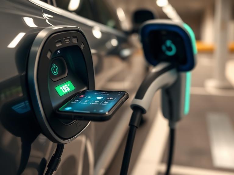
9. Turnkey Procurement & Commissioning Workflow
Deploying commercial EV charging equipment follows a structured installation and testing methodology.
1.Step 1: Utility Load Feasibility & Site Engineering:Weeks 1 – 3.
Evaluate panel headroom, transformer capacity, and conduit routing options. Submit utility interconnection requests for three-phase power service drops.
2.Step 2: Civil Construction & Conduit Installation:Weeks 4 – 8.
Pour concrete equipment pads, dig utility trenches, place underground conduit runs, and pull heavy feeder conductors to mounting locations.
3.Step 3: Hardware Mounting & High-Voltage Termination:Weeks 9 – 11.
Set the charger cabinets on concrete pads, secure structural anchor bolts, terminate high-voltage AC conductors, and wire ground fault monitoring loops.
4.Step 4: Firmware Configuration & OCPP Onboarding:Week 12.
Configure local cellular gateways, assign CPMS security credentials, update equipment firmware, and set dynamic load balancing profiles over OCPP.
5.Step 5: Commissioning & Field Safety Testing:Final Handover.
Perform automated insulation tests, Control Pilot PWM signal verification, ground fault testing, and thermal imaging scans under full charging loads.
10. Frequently Asked Questions (15 Key FAQs)
1. What is included in commercial EV charging equipment?
Commercial EV charging equipment includes the protective physical enclosure, power conversion rectifiers (for DC fast chargers), internal contactors, safety relays, Control Pilot microcontrollers, user interface touchscreens, payment terminals, cables, and connectors.
2. What is the difference between Level 2 AC and DC Fast Charging equipment?
Level 2 equipment delivers AC power to the vehicle’s onboard charger, which converts it to DC for the battery. DC Fast Charging equipment converts AC grid power inside its own cabinet using heavy-duty rectifiers, feeding high-voltage DC power directly to the battery for much faster charging.
3. What is SAE J3400, and why is it important for EV charging equipment?
SAE J3400 is the technical standard for the North American Charging Standard (NACS) connector. It allows a single compact plug to handle both single-phase AC charging and high-power DC fast charging using a shared-pin design, making charging infrastructure more compact and universal.
4. What are Silicon Carbide (SiC) power electronics in DC fast chargers?
Silicon Carbide (SiC) semiconductors replace traditional silicon IGBT transistors in modern DC fast charging power modules. SiC modules operate at higher switching frequencies, generate significantly less heat, achieve over 97% efficiency, and allow for smaller charger cabinets.
5. Why do ultra-fast DC chargers require liquid-cooled cables?
Delivering continuous currents over 300A generates significant heat inside charging cables. Liquid cooling uses internal glycol channels to dissipate this heat, allowing thinner, lighter cables that drivers can move and plug in easily.
6. What is the Megawatt Charging System (MCS)?
MCS is an international charging standard engineered for heavy-duty electric trucks, buses, and marine transport. It supports up to 1,250V and 3,000A, delivering peak power levels up to 3.75 megawatts.
7. What is OCPP, and why should EV charging equipment support it?
The Open Charge Point Protocol (OCPP) is an open communication standard linking charger hardware to cloud management software. Choosing OCPP-compliant equipment prevents vendor lock-in, allowing site hosts to switch software providers without replacing their physical hardware.
8. What is ISO 15118 “Plug & Charge”?
ISO 15118 is a digital communication standard between the vehicle and charger. It enables “Plug & Charge,” allowing the station to automatically authenticate the vehicle and process payment as soon as the cable is plugged in, without needing apps or credit cards.
9. How does dynamic load management work in commercial EV charging equipment?
Dynamic load management uses smart controllers or software to balance available electrical capacity across multiple charging plugs in real time. This allows properties to add more charging ports without exceeding their main utility electrical service limits.
10. Can commercial Level 2 equipment operate on 208V three-phase grid power?
Yes. Most commercial Level 2 chargers are designed to operate on either 240V single-phase residential power or 208V three-phase commercial power systems commonly found in office buildings and parking garages.
11. What NEMA or IP enclosure ratings are required for outdoor EV charging equipment?
Outdoor charging equipment requires at least a NEMA 3R or IP54 rating to protect against rain, snow, blowing dust, and ice formation. Premium commercial equipment often uses NEMA 4X or IP65 enclosures for corrosion resistance in coastal areas.
12. How do credit card payment readers integrate into public EV chargers?
Public charging stations use PCI-DSS compliant credit card terminals (contactless NFC, chip readers, or magnetic strips) connected directly to the station’s main microcontroller. Transaction data is encrypted and sent to payment processing gateways over cellular connections.
13. What is bidirectional charging equipment (V2G/V2H)?
Bidirectional charging equipment uses advanced inverter electronics to flow energy both ways: from the grid to the vehicle, and from the vehicle battery back to a home (V2H), building (V2B), or utility power grid (V2G).
14. What safety protections are built into commercial EV charging hardware?
Key safety features include hardware isolation monitoring, emergency stop buttons, overcurrent relays, overvoltage protection, ground fault circuit interruption (GFCI), surge protection devices (SPD), and cable temperature sensors.
15. How long does commercial EV charging equipment typically last?
With proper routine maintenance, air filter replacements, and regular firmware updates, commercial Level 2 and DC fast charging equipment offers an operational lifespan of 10 to 12 years.